Hardware Connections
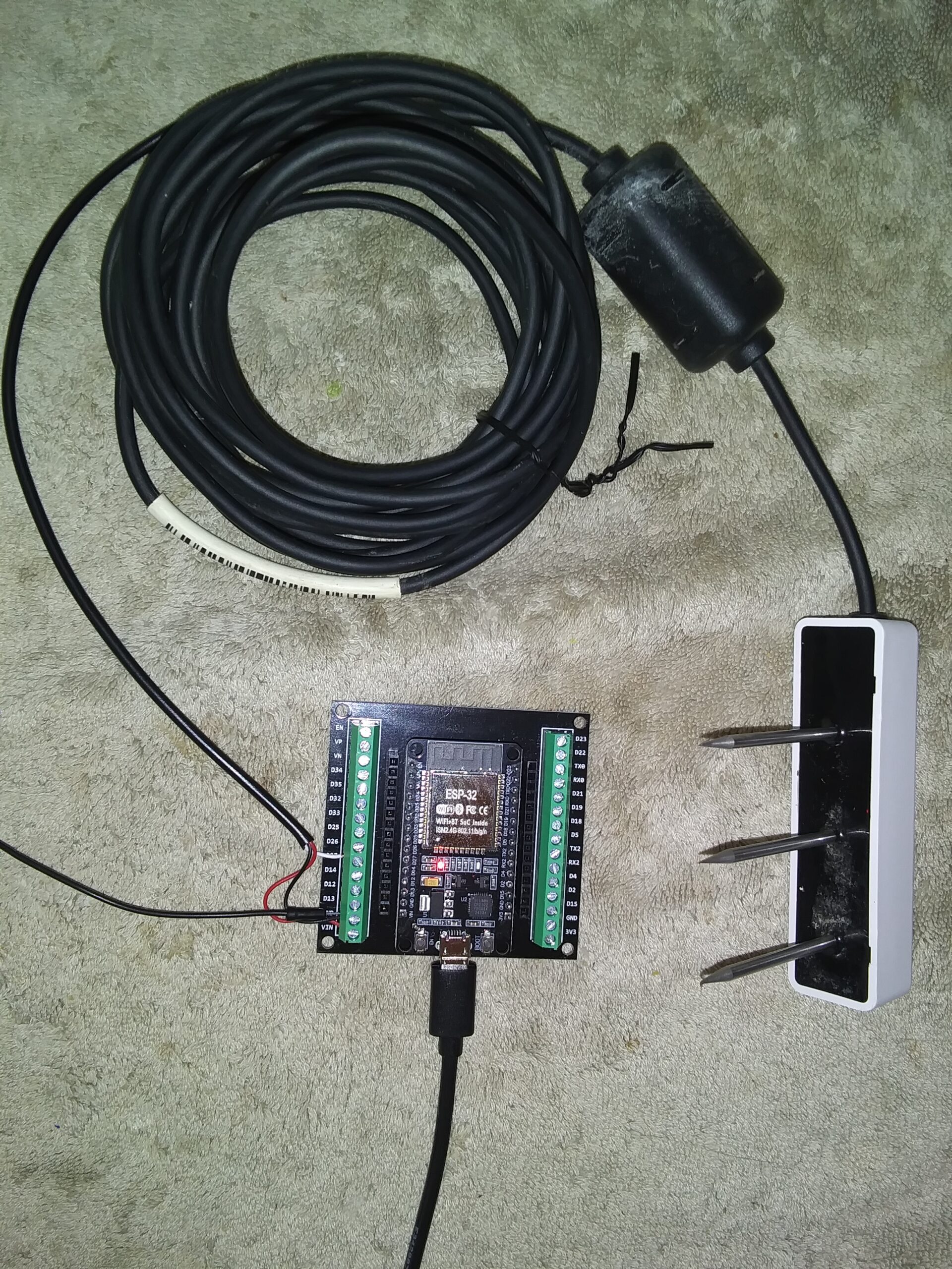
Simple 3 wire hookup!
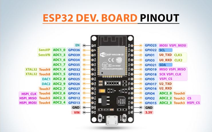
ESP VIN (5V ) – Sensor Red wire power.
ESP – GND – Sensor Blk wire (GND)
ESP GPIO 27, D27 – Sensor White wire data
Teros-12 Spec
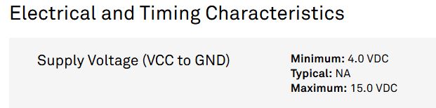
The way I understand the Teros-12 is
- it’s supports older legacy logger system with a DDI Interface
- when the sensor is powered on the sensor sends back a one time DDI msg and then enters SDI mode
- Adruino sample code
- Some of the SDI code had a SDI_PowerPin they were setting high
- Other code had no such pin defined as I assume the power was applied from ESP32 VIN pin of a constant 5V. Always on.
Arduino Code
#include <SDI12.h>
uint32_t serialBaud = 9600;
int8_t dataPin = 27;
char sensorAddress = ‘1’;
SDI12 mySDI12(dataPin);
void setup() {
Serial.begin(serialBaud);
Serial.println(“Open SDI.”);
mySDI12.begin(); delay(500);
}
void loop() {
Serial.println(“\n Hit CLI Enter “);
do { delay(300); }
while (!Serial.available());
Serial.read();
myCommand = (sensorAddress) + “M!”;
mySDI12.sendCommand(myCommand);
delay(300); // wait a while for a response
while (mySDI12.available()) {
char c = mySDI12.read();
if ((c != ‘\n’) && (c != ‘\r’)) {
sdiResponse += c;
}
}
Serial.println(“\t\tresponse = “+sdiResponse);
mySDI12.clearBuffer();
delay(1000);
sdiResponse = “”; // clear the response string
// next command to request data from last measurement
myCommand = String(sensorAddress) + “D0!”;
mySDI12.sendCommand(myCommand);
delay(300); // wait a while for a response
while (mySDI12.available()) {
}
mySDI12.clearBuffer();
}
Teros 12 Sensor
AI Notes